1. Introduction: Why Troubleshooting Matters
A BLDC (Brushless DC) motor controller is the heart of every electric drive system — converting battery power into smooth motion through precise electronic control.
But even the most reliable systems can experience issues caused by wiring, environmental conditions, or component fatigue.
Effective troubleshooting helps:
- Reduce downtime
- Avoid unnecessary replacements
- Extend the lifetime of the motor and controller
At JRAHK, our controllers are designed for robustness — featuring short-circuit protection, temperature monitoring, and intelligent fault detection.
Still, understanding how to diagnose common problems ensures your system stays efficient and safe throughout its service life.
2. Safety First: Before You Begin
Always observe the following before inspecting or repairing a BLDC motor controller:
- Disconnect the battery before opening any connections.
- Use insulated tools and wear anti-static gloves.
- Avoid water or moisture exposure during inspection.
- Check polarity carefully; connecting the battery backward may damage the controller.
- Wait for capacitors to discharge after power-off (about 1–2 minutes).
⚠️ Note: JRAHK controllers contain high-voltage components. Improper handling may cause damage or electric shock. If in doubt, consult a qualified technician.
3. Understanding the Common Controller Faults
A BLDC controller operates through multiple subsystems — power electronics, sensors, logic circuits, and communication.
When any of these areas fails, typical symptoms may appear.
| Symptom | Possible Cause | Quick Check |
|---|---|---|
| Motor does not start | Open circuit, blown fuse, Hall signal missing | Check wiring, Hall connector, and battery output |
| Motor vibrates or jerks | Phase connection error, loose wire, wrong Hall sequence | Verify color coding and re-learn motor direction |
| Motor runs backward | Reversed phase/Hall wiring | Swap any two phase wires or use self-learning mode |
| Controller overheats | Overcurrent, blocked ventilation, oversized load | Measure current draw and check cooling |
| Throttle unresponsive | Faulty throttle signal or 5V reference issue | Test throttle voltage range (0.8V–4.2V) |
| Display shows error code | Communication or sensor fault | Check UART connection and error list |
| Controller burns smell | Shorted MOSFET or reversed connection | Stop immediately, inspect power board |
Each of these issues can often be resolved without replacing the controller — if diagnosed systematically.
4. Step-by-Step Troubleshooting Process
Let’s walk through a logical diagnostic sequence commonly used for JRAHK FOC and sine/square controllers.
Step 1 – Visual Inspection
- Look for loose wires, burn marks, or moisture traces on connectors.
- Ensure the housing screws and heat sink are firmly secured.
- Inspect the MOSFET board (if visible) for signs of discoloration or cracking.
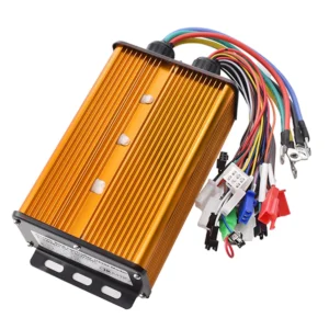
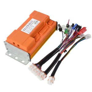
Tip: JRAHK’s gold and blue aluminum housings act as heat sinks; ensure they’re clean and not covered by insulation materials.
Step 2 – Check the Power Supply
- Measure battery voltage with a multimeter.
- Compare with controller’s rated input (e.g., 36V / 48V / 60V / 72V / 84V).
- If voltage is below the controller’s cutoff (usually ~31V for 36V system), it won’t start.
Always verify polarity — reversing positive and negative can cause immediate controller failure.
Step 3 – Test the Throttle
- Connect the throttle to a 5V source and measure the signal voltage:
- Idle: ~0.8V
- Full twist: ~4.2V
- If output is inconsistent or stuck, replace the throttle.
Many JRAHK controllers provide UART feedback, which can display throttle percentage and error codes on the paired display.
Step 4 – Check Motor Phase and Hall Sensor Wiring
- Ensure the three phase wires (usually yellow, green, blue) are correctly matched to the motor.
- Check Hall signal voltage: each signal line should alternate between 0V and 5V when rotating the wheel slowly.
- If any line stays fixed, the Hall sensor may be damaged.
For JRAHK’s dual-mode controllers, you can switch to sensorless mode and verify if the motor starts normally.
This helps confirm whether the issue lies in Hall sensors or wiring.
Step 5 – Self-Learning Function (if available)
Many JRAHK FOC controllers include an auto-learn or self-learning wire:
- Connect the learning wires together.
- Power on the controller.
- The motor will run automatically in one direction, then reverse.
- Disconnect the wires when the correct direction is achieved.
This procedure automatically detects phase sequence and Hall alignment, saving diagnostic time.
Step 6 – Monitor Temperature and Load
- If the controller overheats quickly, check motor resistance (should not be shorted).
- Ensure motor is not mechanically jammed.
- Use a clamp meter to measure phase current; excessive current may indicate FOC tuning or overload issues.
All JRAHK sine-wave and FOC controllers include temperature protection — they reduce output power or shut down if the internal MOSFET temperature exceeds safe limits.
5. Using Display Diagnostics (UART Communication)
If your controller kit includes a display, use it as a diagnostic tool.
The display communicates with the controller through UART and can show:
- Error codes (e.g., E1: throttle error, E2: Hall sensor fault)
- Real-time voltage, speed, and temperature
- Assist mode levels and system status
For instance, pairing a JRAHK Sine BLDC Controller Kit with its corresponding display allows quick error identification without extra tools.
6. Preventive Maintenance Tips
A well-maintained BLDC controller can last many years, even under heavy usage.
Follow these maintenance guidelines for optimal performance:
6.1 Keep It Dry
Avoid water ingress. Although many JRAHK controllers feature sealed aluminum housings, continuous exposure to moisture can corrode connectors and short sensors.
6.2 Maintain Ventilation
Mount the controller in a well-ventilated area. Heat buildup shortens the life of MOSFETs and capacitors.
6.3 Tighten Connections
Loose power or phase terminals increase resistance, generating heat.
Check torque periodically and use anti-vibration washers if mounted on scooters or motorcycles.
6.4 Inspect Cables and Plugs
UV exposure or friction can damage insulation over time. Replace cracked cables immediately.
6.5 Firmware and Calibration
If supported, keep firmware updated to ensure latest safety and efficiency algorithms.
Perform self-learning calibration after motor replacement.
7. When to Replace a Controller
Sometimes replacement is unavoidable. You should consider replacement when:
- MOSFETs are visibly damaged or shorted internally.
- MCU is non-responsive even after reprogramming.
- Burn marks on PCB are extensive.
- Repeated faults persist despite rewiring and testing.
When replacing, ensure the voltage, current, and communication protocol (UART) match your system.
For example:
- 36V 6-Tube model (250–400W) for small e-bikes
- 60V 15-Tube model (1000–2000W) for delivery scooters
- 84V 24-Tube FOC model (up to 5000W) for electric motorcycles
8. Real-World Troubleshooting Scenarios
Scenario A: E-bike motor vibrates but doesn’t start
- Likely cause: incorrect phase/Hall combination.
- Fix: use self-learning function or swap any two phase wires.
Scenario B: Controller heats up even at idle
- Cause: shorted MOSFET or damaged gate driver.
- Fix: measure MOSFET resistance between drain and source; replace defective component.
Scenario C: No response from display
- Cause: UART cable loose or 5V reference missing.
- Fix: check connector continuity and controller’s 5V output.
Scenario D: Throttle stuck at high speed
- Cause: throttle signal shorted to 5V line.
- Fix: inspect throttle cable and replace sensor.
9. Tools You’ll Need
| Tool | Purpose |
|---|---|
| Multimeter | Measure voltage, continuity, and resistance |
| Clamp Meter | Check phase current draw |
| Oscilloscope (optional) | Observe PWM waveforms and Hall signals |
| Insulated Screwdriver | Safe terminal adjustments |
| Heat-conductive Paste | Improve thermal contact with frame |
| Diagnostic Display | View UART error codes and settings |
Having these basic tools can drastically shorten diagnosis time and improve maintenance precision.
10. Why JRAHK Controllers Are Easy to Service
JRAHK designs its controllers with modular logic, clear wiring colors, and self-diagnostic functions, making maintenance easier:
- Dual-mode compatibility: Operates with both sensored and sensorless BLDC motors.
- Self-learning system: Simplifies setup after wiring changes.
- Aluminum heat sink: Efficient cooling, removable for inspection.
- Standardized UART protocol: Compatible with multiple displays.
- Comprehensive protection: Prevents damage from wiring mistakes or overloads.
These engineering features ensure customers and OEM partners can keep their systems running with minimal downtime and straightforward maintenance.
11. Conclusion
Proper maintenance and timely troubleshooting are key to keeping your BLDC system efficient and reliable.
By understanding common faults — from wiring issues to sensor failures — and using diagnostic tools effectively, most problems can be resolved quickly without major repairs.
JRAHK’s BLDC controllers are designed for durability and serviceability, offering powerful protection features and intuitive self-learning capabilities.
With regular inspection and correct installation, your electric bike, scooter, or motorcycle can deliver consistent, smooth performance for years.
A well-maintained controller is not just about longer lifespan — it’s about ensuring safe, efficient, and intelligent electric mobility.